CAN (控制区域总线)
简介
Controller Area Network (CAN),控制器区域总线;
Controller Area Network Flexible Data-Rate (CAN FD),可变数据速率 CAN 总线,向下兼容 CAN1.0,CAN2.0 协议版本;
遵从 ISO 11898-1:2015,ISO 11898-4 标准;
ET6001 共有 2 个 FDCAN 模块,分别编号 CAN0、CAN1。
功能概述
支持11-bit/29-bit 的 ID 类型
CAN FD 模式下最大支持 64-Byte 帧格式
硬件支持 TTCAN Level1,Level2 协议
支持基于同步事件触发的通信
支持 CAN 通信过程错误记录
支持优化的接收帧数据滤波机制
支持 2 个深度可配置的接收 FIFO , 1 个深度可配置的发送 FIFO 和一个深度可配置的事件发送 FIFO
支持可配置的发送队列机制;
支持 SECDED (单 bit 纠错,两 bit 检错)的 ECC 保护机制,支持访问错误地址上报
两个CAN共享 8KB 的 MSG RAM
软件配置流程
基础收发配置流程如下:
配置IOMUX 配置对应串口引脚为CNA模式
设置 CAN 为软件初始化模式 调用
CAN_setOpMode()传入CANx及 CAN_OPERATION_MODE_SW_INIT初始化 CAN 模块 调用
CAN_init()传入CANx及参数结构体指针配置位计时 调用
CAN_setBitTime()传入CANx及参数结构体指针配置 CAN 模块 调用
CAN_config()传入CANx及参数结构体指针配置 MSG RAM 调用
CAN_msgRAMConfig()传入CANx及参数结构体指针配置 ID 元素过滤
调用
CAN_addStdMsgIDFilter()配置标准ID 元素过滤调用
CAN_addExtMsgIDFilter()配置扩展ID 元素过滤
设置 CAN 为正常模式 调用
CAN_setOpMode()传入CANx及 CAN_OPERATION_MODE_NORMAL将发送的数据写入到MSG RAM 调用
CAN_writeMsgRam()传入相关参数添加发送请求 调用
CAN_txBufAddReq()传入CANx及缓冲区号等待数据接收 调用
CAN_getRxFIFOStatus()查看FIFO状态,当 rxFIFOStatus.fillLvl 大于 0 时, 调用CAN_readMsgRam()读取数据向RXFIFO发送确认 调用
CAN_writeRxFIFOAck()传入CANx及缓冲区号、状态
CAN波特率计算
CAN 波特率计算公式如下:
其中,TimeSeg1 和 TimeSeg2 分别为时间段 1 和时间段 2 的长度。
SynchJumpWidth是同步跳转宽度,通常设置为与 TimeSeg2 相同的值。
CAN 的采样点是在TimeSeg1 和 TimeSeg2 之间的一个点,通常选择在TimeSeg1 的中间位置。采样点的计算公式如下:
- 采样点的设置选取建议:
一般配置在75-80%的位置
选择采样点位置在85%左右为佳
波特率 > 800K:75% 波特率 > 500K:80% 波特率 <= 500K:87.5%
CAN Clock在没有修改system_et6x.c中时钟分频配置的情况下,默认是 40MHz。
发射器延迟补偿(TDC)
在传统 CAN 或 CAN FD 的仲裁阶段,节点需要在位时间的 采样点 (Sample Point) 读取总线电平并与自己发送的位进行比较以检测错误(如位错误、填充错误等)。
发送器延迟 (Transmitter Delay): 信号从发送引脚 (m_ttcan_tx) 发出,经过 CAN 收发器的物理电路,到达接收引脚 (m_ttcan_rx) 是需要时间的。
这个时间差称为发送器延迟。它主要由收发器内部的传播延迟决定。
如果这个发送器延迟大于采样点之前的时间段 (TSEG1),那么发送节点在采样点看到的 m_ttcan_rx 电平可能还不是它刚刚发送到 m_ttcan_tx 上的位。 这会导致发送节点错误地检测到一个 位错误 (Bit Error),即使物理总线传输是正常的。使得 CAN FD 数据阶段能达到的最高比特率直接受限于收发器的延迟。 为了追求更高的数据速率(更短的位时间),使用 发送器延迟补偿 (TDC) 来解决这个延迟带来的问题。
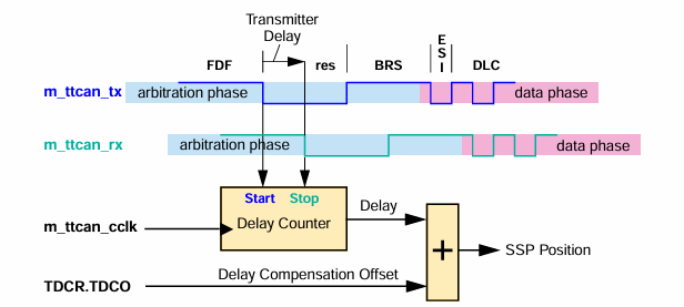
TDC(发射器延迟补偿) 仅在 CAN FD 帧的数据阶段有效。在仲裁阶段(传统 CAN 或 CAN FD 的 ID 仲裁部分),TDC 始终禁用,使用常规采样点。
TDCF:启用发射器延迟补偿滤波器窗口, 过滤在接收到的 FDF 位内出现的短暂的显性毛刺,防止计数器错误地提前停止,导致测得的延迟值偏小,进而使 SSP 位置太靠前,失去补偿效果。 这定义了 SSP 位置的最小值。 如果 TDCF 大于 TDCO时该功能被启用。
TDCO:发射器延迟补偿偏移量。
TDCV:发射器延迟补偿值,由从 m_ttcan_tx 到 m_ttcan_rx 的测量延迟与 TDCO 之和确定。
SSP:次级采样点位置。SSP <= 127mtq && SSP <= 数据位时间 + 6mtq,即 TDCV <= 数据位时间 + 6mtq。
数据位时间计算公式:
以CAN总线时钟40MHZ,数据波特率4Mbps为例:
数据位时间: 40MHz / 4M = 10mtq
假设从 m_ttcan_tx 到 m_ttcan_rx 的测量延迟为8mtq
若数据采样点为80%,则常规采样点: 10mtq * 80% = 8mtq,此时
延迟值 <= 常规采样点能采样到正确数据,不需要启用TDC补偿。若数据采样点为60%,则常规采样点: 10mtq * 60% = 6mtq,此时
延迟值 > 常规采样点常规采样点采样到错误数据,需要启用TDC补偿。次级采样点:SSP的位置应当为 8 ~ (10mtq + 6mtq) ,即 8 ~ 16mtq
通过TDCO将次级采样点(SSP)调整到8~16mtq,即 TDCO 可配置为 2~10 mtq。
为防止 FDF 位内出现的短暂的显性毛刺,可将TDCF 设置为 8~spp mtq。TDCF>TDCO时,TDCF功能启用。
发射器延迟补偿示例代码:
CAN_InitParams initParams;
initParams.tdcEnable         = ENABLE;              // Transmitter Delay Compensation is enabled.
// Transmitter Delay Compensation parameters.
initParams.tdcConfig.tdcf    = 0xAU;                // Transmitter Delay Compensation Filter Window Length
                                                    // The feature is enabled when TDCF is configured to a value greater thanTDCO.
initParams.tdcConfig.tdco    = 0x6U;                // Transmitter Delay Compensation SSP Offset
CAN_init(CAN0, &initParams);
切换 CAN 为正常模式时,TDCV 会被清除,在使能发射器延迟补偿后,每次 FD 帧传输都会更新。
可通过代码获取 TDCV 值,并调整 TDCO 以补偿 TDCV。
uint8_t tdcv;
CAN_ProtocolStatus protStatus;
CAN_getProtocolStatus(CAN0,&protStatus);
tdcv = protStatus.tdcv;
使用CAN FD模式
使能CAN FD,不使能波特率切换,此时仲裁波特率与数据波特率一致(固定为仲裁波特率)。
使能CAN FD,使能波特率切换,此时仲裁波特率与数据波特率可以不一致。
备注
当使用CAN FD加速,且数据波特率较高时,需启用发射器延迟补偿
使用CAN FD并启用发射器延迟补偿示例代码如下:
initParams.fdMode            = CAN_FD_CAN;          // FD operation enabled.
initParams.brsEnable         = CAN_BRS_ENABLE;      // Bit rate switching for transmissions enabled
initParams.tdcEnable         = ENABLE;              // Transmitter Delay Compensation is enabled.
initParams.wdcPreload        = 0xFFU;               // Start value of the Message RAM Watchdog Counter preload.
// Transmitter Delay Compensation parameters.
initParams.tdcConfig.tdcf    = 0xAU;                // Transmitter Delay Compensation Filter Window Length
                                                    // The feature is enabled when TDCF is configured to a value greater thanTDCO.
initParams.tdcConfig.tdco    = 0x6U;                // Transmitter Delay Compensation SSP Offset
CAN_init(CAN0, &initParams);
DLC 在 CAN FD 中的编码
在 CAN FD 格式中,DLC 的编码与标准 CAN 格式不同。DLC 为 0 到 8 时的编码与标准 CAN 相同,码值 9 到 15,在标准 CAN 中所有编码都表示 8 字节的数据字段, 但在 CAN FD 中,这些码值表示的数据字段长度不同。具体如下:
DLC |
9 |
10 |
11 |
12 |
13 |
14 |
15 |
|---|---|---|---|---|---|---|---|
数据字节数 |
12 |
16 |
20 |
24 |
32 |
48 |
64 |
应用示例
CAN 外部回环示例:CAN/CAN_init_TxRx。
CAN 接收中断示例:CAN/CAN_init_IT_receive。
CAN 接收数据到BUFFER示例: CAN/CAN_init_receive_multiple-buffers。
CAN 接收高优先级和水位标志中断:CAN/CAN_init_receive_priority_watermark。
CAN 优先级发送和水位标志中断:CAN/CAN_init_transmit_priority_watermark。
API Reference
Header File
Functions
-
uint32_t CAN_isFDOpEnable(CAN_Type *CANx)
This API will return flexible data rate operation status CAN module.
- 返回:
uint32_t Returns TRUE if flexible data rate operation is enabled. Else returns FALSE.
-
void CAN_setOpMode(CAN_Type *CANx, uint32_t mode)
This API will set CAN module mode of operation.
- 参数:
CANx – Pointer to the CAN peripheral.
mode – Mode of operation. Refer enum CAN_OperationMode.
-
uint32_t CAN_getOpMode(CAN_Type *CANx)
This API will return CAN module mode of operation.
- 参数:
CANx – Pointer to the CAN peripheral.
- 返回:
mode Mode of operation. Refer enum CAN_OperationMode.
-
int32_t CAN_init(CAN_Type *CANx, const CAN_InitParams *initParams)
This API will initialize CAN module.
- 参数:
CANx – Pointer to the CAN peripheral.
initParams – Initialization parameters. Refer struct CAN_InitParams.
- 返回:
int32_t Initialization status.
-
int32_t CAN_config(CAN_Type *CANx, const CAN_ConfigParams *configParams)
This API will configure CAN module.
- 参数:
CANx – Pointer to the CAN peripheral.
configParams – configuration parameters. Refer struct CAN_ConfigParams.
- 返回:
int32_t Configuration status.
-
int32_t CAN_setBitTime(CAN_Type *CANx, const CAN_BitTimingParams *configParams)
This API will configure a bit timings for CAN module.
- 参数:
CANx – Pointer to the CAN peripheral.
configParams – Configuration parameters for CAN bit timing. Refer struct CAN_BitTimingParams.
- 返回:
int32_t Bit Timings configuration status.
-
int32_t CAN_msgRAMConfig(CAN_Type *CANx, const CAN_MsgRAMConfigParams *msgRAMConfigParams)
This API will configure Different sections of Message RAM.
- 参数:
CANx – Pointer to the CAN peripheral.
msgRAMConfigParams – Message RAM Configuration parameters. Refer struct CAN_MsgRAMConfigParams.
- 返回:
int32_t Configuration Status.
-
int32_t CAN_setExtIDAndMask(CAN_Type *CANx, uint32_t idMask)
This API will configure Extended ID AND Mask.
- 参数:
CANx – Pointer to the CAN peripheral.
idMask – Configuration parameters for CAN Extended Id mask. This value is 29 bit wide.
- 返回:
int32_t Extended ID AND Mask configuration status.
-
void CAN_writeMsgRam(CAN_Type *CANx, uint32_t memType, uint32_t bufNum, const CAN_TxBufElement *elem)
This API is used to write Tx message to message RAM.
- 参数:
CANx – Pointer to the CAN peripheral.
memType – Part of message ram to which given message to write. Refer enum CAN_MemType.
bufNum – Buffer number where message to write. This parameter will ignored if memType is FIFO/Q.
elem – Message Object. Refer struct CAN_TxBufElement.
-
int32_t CAN_txBufAddReq(CAN_Type *CANx, uint32_t bufNum)
This API will set Tx Buffer Add Request.
备注
The function assumes that the CAN peripheral is already initialized and the transmit buffer is not full.
备注
The function also assumes that the CCE bit in the TXBAR register is ‘0’ and does not need to be reverted.
- 参数:
CANx – Pointer to the CAN peripheral.
bufNum – Tx Buffer number for which request is to be added.
- 返回:
DRV_OK if the message was successfully added to the buffer.
- 返回:
DRV_ERROR if the buffer number is invalid.
-
void CAN_getNewDataStatus(CAN_Type *CANx, CAN_RxNewDataStatus *newDataStatus)
This API get New Data Message Status.
- 参数:
CANx – Pointer to the CAN peripheral.
newDataStatus – Rx Buffer new data status.
-
void CAN_clearNewDataStatus(CAN_Type *CANx, const CAN_RxNewDataStatus *newDataStatus)
This API clear New Data Message Status.
- 参数:
CANx – Pointer to the CAN peripheral.
newDataStatus – Rx Buffer new data status. Refer struct CAN_RxNewDataStatus.
-
void CAN_readMsgRam(CAN_Type *CANx, uint32_t memType, uint32_t bufNum, uint32_t fifoNum, CAN_RxBufElement *elem)
This API is used to read received message from Message RAM.
- 参数:
CANx – Pointer to the CAN peripheral.
memType – Part of message ram to which given message to write. Refer enum CAN_MemType.
bufNum – Buffer number from where message is to read. This parameter will ignored if memType is FIFO/Q.
fifoNum – FIFOs number from where message is to read. Refer enum CAN_RxFIFONum. This parameter will ignored if memType is buffer.
elem – Message Object. Refer struct CAN_RxBufElement.
-
void CAN_readHighPriorityMsgRam(CAN_Type *CANx, CAN_RxBufElement *elem)
This API will read the High Priority message object from Message RAM.
- 参数:
CANx – Pointer to the CAN peripheral.
elem – Message Object. Refer struct CAN_RxBufElement.
-
void CAN_readTxEventFIFO(CAN_Type *CANx, CAN_TxEventFIFOElement *txEventElem)
This API is used to read from Tx Event FIFO.
- 参数:
CANx – Pointer to the CAN peripheral.
txEventElem – Tx Event FIFO Message Object. Refer struct CAN_TxEventFIFOElement.
-
void CAN_addStdMsgIDFilter(CAN_Type *CANx, uint32_t filtNum, const CAN_StdMsgIDFilterElement *elem)
This API is used to add Extended Message ID Filter Element.
- 参数:
CANx – Pointer to the CAN peripheral.
filtNum – Filter number.
elem – Filter Object. Refer struct CAN_ExtMsgIDFilterElement.
-
void CAN_addExtMsgIDFilter(CAN_Type *CANx, uint32_t filtNum, const CAN_ExtMsgIDFilterElement *elem)
This API is used to add Extended Message ID Filter Element.
- 参数:
CANx – Pointer to the CAN peripheral.
filtNum – Filter number.
elem – Filter Object. Refer struct CAN_ExtMsgIDFilterElement.
-
void CAN_enbaleLpbkMode(CAN_Type *CANx, uint32_t lpbkMode, uint32_t enable)
This API will enable/disable Loop Back Test Mode for CAN module.
备注
This API can be called only when CAN module is in Software Initialization mode of operation.
- 参数:
CANx – Pointer to the CAN peripheral.
lpbkMode – Loopback mode for CAN. CAN_LpbkMode.
enable – Loop Back Mode is enabled if it is TRUE. Loop Back Mode is disabled if it is FALSE.
-
void CAN_getErrCounters(CAN_Type *CANx, CAN_ErrCntStatus *errCounter)
This API will return error counter status for CAN module.
- 参数:
CANx – Pointer to the CAN peripheral.
errCounter – Error Counter Status. Refer struct CAN_ErrCntStatus.
-
void CAN_getProtocolStatus(CAN_Type *CANx, CAN_ProtocolStatus *protStatus)
This API will return protocol status for CAN module.
- 参数:
CANx – Pointer to the CAN peripheral.
protStatus – Protocol Status. Refer struct CAN_ProtocolStatus.
-
void CAN_enableIntr(CAN_Type *CANx, uint32_t intrMask, uint32_t enable)
This API is used to enable/disable interrupts.
- 参数:
CANx – Pointer to the CAN peripheral.
intrMask – Interrupts to enable. Refer enum CAN_IntrSrc.
enable – Interrupt is enabled if it is TRUE. Interrupt is disabled if it is FALSE.
-
void CAN_selectIntrLine(CAN_Type *CANx, uint32_t intrMask, uint32_t lineNum)
This API is used to select interrupt line.
- 参数:
CANx – Pointer to the CAN peripheral.
intrMask – Interrupt Number for which interrupt line is to be selected. Refer enum CAN_IntrSrc.
lineNum – Interrupt Line to select. Refer enum CAN_IntrLineNum,
-
uint32_t CAN_getIntrLineSelectStatus(CAN_Type *CANx)
This API is used to get interrupt line selected for each interrupt.
- 参数:
CANx – Pointer to the CAN peripheral.
- 返回:
uint32_t Interrupt Line Select Status.
-
void CAN_enableIntrLine(CAN_Type *CANx, uint32_t lineNum, uint32_t enable)
This API is used to enable/disable selected interrupt line.
- 参数:
CANx – Pointer to the CAN peripheral.
lineNum – Interrupt Line to select. Refer enum CAN_IntrLineNum,
enable – Interrupt Line is enabled if it is 1. Interrupt Line is disabled if it is 0.
-
uint32_t CAN_getIntrStatus(CAN_Type *CANx)
This API will return interrupt status.
- 参数:
CANx – Pointer to the CAN peripheral.
- 返回:
uint32_t Interrupt Status.
-
void CAN_clearIntrStatus(CAN_Type *CANx, uint32_t intrMask)
This API is used to clear the interrupt status.
- 参数:
CANx – Pointer to the CAN peripheral.
intrMask – Interrupts to clear status.
- 返回:
None.
-
void CAN_getHighPriorityMsgStatus(CAN_Type *CANx, CAN_HighPriorityMsgInfo *hpm)
This API will return High Priority Message Status.
- 参数:
CANx – Pointer to the CAN peripheral.
hpm – High Priority Message Status. Refer struct CAN_HighPriorityMsgInfo.
-
void CAN_getRxFIFOStatus(CAN_Type *CANx, CAN_RxFIFOStatus *fifoStatus)
This API will Rx FIFO status.
- 参数:
CANx – Pointer to the CAN peripheral.
fifoStatus – Rx FIFO Status. Refer struct CAN_RxFIFOStatus.
-
int32_t CAN_writeRxFIFOAck(CAN_Type *CANx, uint32_t fifoNum, uint32_t idx)
This API will write Rx FIFO Acknowledgement.
- 参数:
CANx – Pointer to the CAN peripheral.
fifoNum – FIFO Number.
idx – Rx FIFO Acknowledge Index
- 返回:
status Acknowledgement Status.
-
void CAN_getTxFIFOQueStatus(CAN_Type *CANx, CAN_TxFIFOStatus *fifoStatus)
This API will Tx FIFO status.
- 参数:
CANx – Pointer to the CAN peripheral.
fifoStatus – Tx FIFO Status. CAN_TxFIFOStatus.
- 返回:
None.
-
uint32_t CAN_getTxBufReqPend(CAN_Type *CANx)
This API will return Tx Buffer Request Pending status.
- 参数:
CANx – Pointer to the CAN peripheral.
- 返回:
status Tx Buffer Request Pending status.
-
int32_t CAN_txBufCancellationReq(CAN_Type *CANx, uint32_t buffNum)
This API will set Tx Buffer Cancellation Request.
- 参数:
CANx – Pointer to the CAN peripheral.
buffNum – Tx Buffer number for which request is to be added.
- 返回:
int32_t Configuration Status.
-
uint32_t CAN_getTxBufTransmissionStatus(CAN_Type *CANx)
This API will return Tx Buffer Transmission Occurred status.
- 参数:
CANx – Pointer to the CAN peripheral.
- 返回:
uint32_t Tx Buffer Transmission Occurred status.
-
uint32_t CAN_txBufCancellationStatus(CAN_Type *CANx)
This API will return Transmit Buffer Cancellation Finished status.
- 参数:
CANx – Pointer to the CAN peripheral.
- 返回:
uint32_t Transmit Buffer Cancellation Finished status.
-
int32_t CAN_txBufTransIntrEnable(CAN_Type *CANx, uint32_t bufNum, uint32_t enable)
This API is used to enable/disable Tx Buffer Transmission Interrupt.
- 参数:
CANx – Pointer to the CAN peripheral.
bufNum – Buffer number for which interrupt is to enable.
enable – Interrupt is enabled if it is TRUE. Interrupt is disabled if it is FALSE.
- 返回:
int32_t Configuration status.
-
int32_t CAN_getTxBufCancellationIntrEnable(CAN_Type *CANx, uint32_t bufNum, uint32_t enable)
This API is used to enable/disable Tx Buffer Cancellation Finished Interrupt.
- 参数:
CANx – Pointer to the CAN peripheral.
bufNum – Buffer number for which interrupt is to enable.
enable – Interrupt is enabled if it is TRUE. Interrupt is disabled if it is FALSE.
- 返回:
int32_t Configuration status.
-
void CAN_getTxEventFIFOStatus(CAN_Type *CANx, CAN_TxEventFIFOStatus *fifoStatus)
This API will Tx Event FIFO status.
- 参数:
CANx – Pointer to the CAN peripheral.
fifoStatus – Tx Event FIFO Status. CAN_TxEventFIFOStatus.
-
void CAN_addClockStopRequest(CAN_Type *CANx, uint32_t enable)
This API add clock stop request for CAN module to put it in power down mode.
- 参数:
CANx – Pointer to the CAN peripheral.
enable – Add CLock Stop Request. Adds Clock Clock stop Request is TRUE otherwise removes it.
-
int32_t CAN_writeTxEventFIFOAck(CAN_Type *CANx, uint32_t idx)
This API will write Event FIFO Acknowledge Index.
- 参数:
CANx – Pointer to the CAN peripheral.
idx – Event FIFO Acknowledge Index
- 返回:
int32_t Acknowledgement Status.
-
uint32_t CAN_getClockStopAck(CAN_Type *CANx)
This API get clock stop acknowledgement for CAN module. It return whether CAN is power down mode or not.
- 参数:
CANx – Pointer to the CAN peripheral.
- 返回:
uint32_t Return Clock Stop Acknowledgement status. Return ‘1’ if module is set in power down mode else returns ‘0’.
-
uint32_t CAN_getRxPinState(CAN_Type *CANx)
This API will return Rx pin state of CAN module.
- 参数:
CANx – Pointer to the CAN peripheral.
- 返回:
state CAN Rx Pin State. 0= The CAN bus is dominant 1= The CAN bus is recessive
-
void CAN_setTxPinState(CAN_Type *CANx, uint32_t state)
This API will set Tx pin state of CAN module.
- 参数:
CANx – Pointer to the CAN peripheral.
state – CAN Tx Pin State. 00= Reset value 01= Sample Point can be monitored at tx pin 10= The CAN bus is dominant 11= The CAN bus is recessive other= It will treated as 11.
-
uint32_t CAN_getTxPinState(CAN_Type *CANx)
This API will return Tx pin state of CAN module.
- 参数:
CANx – Pointer to the CAN peripheral.
- 返回:
state CAN Tx Pin State. 00= Reset value 01= Sample Point can be monitored at tx pin 10= The CAN bus is dominant 11= The CAN bus is recessive
-
uint32_t CAN_getTSCounterVal(CAN_Type *CANx)
This API will return current timestamp counter value.
- 参数:
CANx – Pointer to the CAN peripheral.
- 返回:
uint32_t Current Timestamp counter value.
-
uint32_t CAN_getClkStopAck(CAN_Type *CANx)
This API will return clock stop acknowledgement for CAN module.
- 参数:
CANx – Pointer to the CAN peripheral.
- 返回:
uint32_t Clock Stop Acknowledge 0= No clock stop acknowledged 1= M_CAN may be set in power down
-
void CAN_getBitTime(CAN_Type *CANx, CAN_BitTimingParams *configParams)
This API will get the configured bit timings for CAN module.
- 参数:
CANx – Pointer to the CAN peripheral.
configParams – Configuration parameters for CAN bit timing. CAN_BitTimingParams.
- 返回:
None.
-
void CAN_resetTSCounter(CAN_Type *CANx)
This API will reset timestamp counter value.
- 参数:
CANx – Pointer to the CAN peripheral.
-
uint32_t CAN_getTOCounterVal(CAN_Type *CANx)
This API will return current time-out counter value.
- 参数:
CANx – Pointer to the CAN peripheral.
- 返回:
uint32_t Current Time-out counter value.
-
uint32_t CAN_getEndianVal(CAN_Type *CANx)
This function return endianness value of CAN module.
- 返回:
uint32_t Endianness value. (0x87654321)
-
uint32_t CAN_getExtIDANDMask(CAN_Type *CANx)
This API will get the configured Extended ID AND Mask.
- 参数:
CANx – Pointer to the CAN peripheral.
- 返回:
idMask Extended ID AND Mask.
-
uint32_t CAN_getMsgObjSize(uint32_t elemSize)
Get message object size.
- 参数:
elemSize – Element Size
- 返回:
uint32_t message object size
-
void CAN_enableDMUIntr(CAN_Type *CANx, uint32_t intrMask, uint32_t enable)
Enable or disable the DMU interrupt.
- 参数:
CANx – Transfer with TSU Time stamp
intrMask – Refer enum CAN_IntrSrc or CAN_DMU_INTR_MASK_ALL
enable – enable or disable
-
void CAN_enableDMUTransferTS(CAN_Type *CANx, uint32_t enable)
configure for DMU Transfer with TSU Time stamp
- Attention
CAN_ConfigParams.tsSelect must use External timestamp counter when enable DMU TTS
- 参数:
CANx – Pointer to the CAN peripheral.
enable – enable or disable transfer with TSU time stamp
-
int32_t CAN_configTSU(CAN_Type *CANx, const CAN_TSUConfigParams *configParams)
This API will configure CAN TSU Unit.
- Attention
CAN_ConfigParams.tsSelect must use External timestamp counter when config TSU
- 参数:
CANx – Pointer to the CAN peripheral.
configParams – [in]
- 返回:
int32_t
-
void CAN_setDMURxRequest(CAN_Type *CANx, CAN_DMURxRequest Request)
Select DMU Rx Request type.
- 参数:
CANx – Pointer to the CAN peripheral.
Request – Refer enum CAN_DMURxRequest
-
void CAN_copyMsgToBuffer(const CAN_TxBufElement *elem, uint32_t *buffer)
Copy CAN_TxBufElement message to a buffer.
- 参数:
elem – [in] Message Object. Refer struct CAN_TxBufElement.
buffer – [out] buffer storeed message
-
void CAN_copyBufferToMsg(uint32_t *buffer, CAN_RxBufElement *elem)
Copy message in buffer to CAN_RxBufElement structure element.
- 参数:
buffer – [in] buffer storeed message
elem – [out] CAN_RxBufElement element
Structures
-
struct CAN_TDCConfig
Structure for CAN Transmitter Delay Compensation parameters.
-
struct CAN_GlobalFiltConfig
Structure for CAN Global Filter Configuration parameters.
Public Members
-
uint32_t rrfe
Reject Remote Frames Extended 0 = Filter remote frames with 29-bit extended IDs 1 = Reject all remote frames with 29-bit extended IDs
-
uint32_t rrfs
Reject Remote Frames Standard 0 = Filter remote frames with 11-bit standard IDs 1 = Reject all remote frames with 11-bit standard IDs
-
uint32_t anfe
Accept Non-matching Frames Extended 0 = Accept in Rx FIFO 0 1 = Accept in Rx FIFO 1 others = Reject
-
uint32_t anfs
Accept Non-matching Frames Standard 0 = Accept in Rx FIFO 0 1 = Accept in Rx FIFO 1 others = Reject
-
uint32_t rrfe
-
struct CAN_ECCConfigParams
Structure for CAN ECC configuration parameters.
-
struct CAN_BitTimingParams
Structure for bit timing calculation. Bit timing related to data phase will be valid only in case where CAN is put in CAN-FD mode and will be ‘0’ otherwise.
Public Members
-
uint32_t nomRatePrescalar
Nominal Baud Rate Pre-scaler Range:[0x0-0x1FF]
-
uint32_t nomTimeSeg1
Nominal Time segment before sample point Range:[0x0-0xFF]
-
uint32_t nomTimeSeg2
Nominal Time segment after sample point Range:[0x0-0x7F]
-
uint32_t nomSynchJumpWidth
Nominal (Re)Synchronization Jump Width Range:[0x0-0x7F]
-
uint32_t dataRatePrescalar
Data Baud Rate Pre-scaler Range:[0x0-0x1F]
-
uint32_t dataTimeSeg1
Data Time segment before sample point Range:[0x0-0x1F]
-
uint32_t dataTimeSeg2
Data Time segment after sample point Range:[0x0-0xF]
-
uint32_t dataSynchJumpWidth
Data (Re)Synchronization Jump Width Range:[0x0-0xF]
-
uint32_t nomRatePrescalar
-
struct CAN_MsgRAMConfigParams
Structure for CAN Message RAM Configuration Parameters. Message RAM can contain following sections: Standard ID filters, Extended ID filters, TX FIFO(or TX Q), TX Buffers, TX EventFIFO, RX FIFO0, RX FIFO1, RX Buffer. Note: If particular section in the RAM is not used then it’s size should be initialized to ‘0’ (Number of buffers in case of Tx/Rx buffer).
Public Members
-
uint32_t flssa
Standard ID Filter List Start Address
-
uint32_t lss
List Size: Standard ID 0 = No standard Message ID filter 1-127 = Number of standard Message ID filter elements others = Values greater than 128 are interpreted as 128
-
uint32_t flesa
Extended ID Filter List Start Address
-
uint32_t lse
List Size: Extended ID 0 = No standard Message ID filter 1-64 = Number of standard Message ID filter elements others = Values greater than 64 are interpreted as 64
-
uint32_t txStartAddr
Tx Buffers Start Address
-
uint32_t txBufNum
Number of Dedicated Transmit Buffers 0 = No Dedicated Tx Buffers 1-32 = Number of Dedicated Tx Buffers others = Values greater than 32 are interpreted as 32
-
uint32_t txFIFOSize
Transmit FIFO/Queue Size 0 = No Tx FIFO/Queue 1-32 = Number of Tx Buffers used for Tx FIFO/Queue others = Values greater than 32 are interpreted as 32
-
uint32_t txBufMode
Tx FIFO/Queue Mode 0 = Tx FIFO operation 1 = Tx Queue operation
-
uint32_t txBufElemSize
Tx Buffer Element Size
-
uint32_t txEventFIFOStartAddr
Tx Event FIFO Start Address
-
uint32_t txEventFIFOSize
Event FIFO Size 0 = Tx Event FIFO disabled 1-32 = Number of Tx Event FIFO elements others = Values greater than 32 are interpreted as 32
-
uint32_t txEventFIFOWaterMark
Tx Event FIFO Watermark 0 = Watermark interrupt disabled 1-32 = Level for Tx Event FIFO watermark interrupt others = Watermark interrupt disabled
-
uint32_t rxFIFO0startAddr
Rx FIFO0 Start Address
-
uint32_t rxFIFO0size
Rx FIFO0 Size 0 = No Rx FIFO 1-64 = Number of Rx FIFO elements others = Values greater than 64 are interpreted as 64
-
uint32_t rxFIFO0waterMark
Rx FIFO0 Watermark 0 = Watermark interrupt disabled 1-63 = Level for Rx FIFO 0 watermark interrupt others = Watermark interrupt disabled
-
uint32_t rxFIFO0OpMode
Rx FIFO0 Operation Mode 0 = FIFO blocking mode 1 = FIFO overwrite mode
-
uint32_t rxFIFO1startAddr
Rx FIFO1 Start Address
-
uint32_t rxFIFO1size
Rx FIFO1 Size 0 = No Rx FIFO 1-64 = Number of Rx FIFO elements others = Values greater than 64 are interpreted as 64
-
uint32_t rxFIFO1waterMark
Rx FIFO1 Watermark 0 = Watermark interrupt disabled 1-63 = Level for Rx FIFO 1 watermark interrupt others = Watermark interrupt disabled
-
uint32_t rxFIFO1OpMode
Rx FIFO1 Operation Mode 0 = FIFO blocking mode 1 = FIFO overwrite mode
-
uint32_t rxBufStartAddr
Rx Buffer Start Address
-
uint32_t rxBufElemSize
Rx Buffer Element Size
-
uint32_t rxFIFO0ElemSize
Rx FIFO0 Element Size
-
uint32_t rxFIFO1ElemSize
Rx FIFO1 Element Size
-
uint32_t flssa
-
struct CAN_InitParams
Structure for CAN initialization parameters.
Public Members
-
uint32_t fdMode
FD Operation Enable 0 = FD operation disabled 1 = FD operation enabled
-
uint32_t brsEnable
Bit Rate Switch Enable This is valid only when opMode = 1. 0 = Bit rate switching for transmissions disabled 1 = Bit rate switching for transmissions enabled
-
uint32_t txpEnable
Transmit Pause 0 = Transmit pause disabled 1 = Transmit pause enabled
-
uint32_t efbi
FEdge Filtering during Bus Integration 0 = Edge filtering disabled 1 = Two consecutive dominant tq required to detect an edge for hard synchronization
-
uint32_t pxhddisable
Protocol Exception Handling Disable 0 = Protocol exception handling enabled 1 = Protocol exception handling disabled
-
uint32_t darEnable
Disable Automatic Retransmission 0 = Automatic retransmission of messages not transmitted successfully enabled 1 = Automatic retransmission disabled
-
uint32_t wdcPreload
Start value of the Message RAM Watchdog Counter Range:[0x0-0xFF]
-
CAN_TDCConfig tdcConfig
Transmitter Delay Compensation parameters. Refer struct CAN_TDCConfig.
-
uint32_t tdcEnable
Transmitter Delay Compensation Enable 0 = Transmitter Delay Compensation is disabled 1 = Transmitter Delay Compensation is enabled
-
uint32_t fdMode
-
struct CAN_ConfigParams
Structure for CAN configuration parameters.
Public Members
-
uint32_t monEnable
Bus Monitoring Mode 0 = Bus Monitoring Mode is disabled 1 = Bus Monitoring Mode is enabled
-
uint32_t asmEnable
Restricted Operation Mode 0 = Normal CAN operation 1 = Restricted Operation Mode active This mode should not be combined with test modes.
-
uint32_t tsPrescalar
Timestamp Counter Prescaler. Range:[0x0-0xF]
-
uint32_t tsSelect
Timestamp source selection. 00= Timestamp counter value always 0x0000 01= Timestamp counter value incremented according to tsPrescalar 10= External timestamp counter value used 11= Same as “00”
-
uint32_t timeoutSelect
Time-out counter source select. Refer enum CAN_TimeOutSelect.
-
uint32_t timeoutPreload
Start value of the Timeout Counter (down-counter). The Timeout Counter is decremented in multiples of CAN bit times [1-16] depending on the configuration of the tsPrescalar. Range:[0x0-0xFFFF]
-
uint32_t timeoutCntEnable
Time-out Counter Enable 0 = Time-out Counter is disabled 1 = Time-out Counter is enabled
-
CAN_GlobalFiltConfig filterConfig
Global Filter Configuration parameters. Refer struct CAN_GlobalFiltConfig.
-
uint32_t monEnable
-
struct CAN_ErrCntStatus
Structure for CAN error logging counters status.
Public Members
-
uint32_t transErrLogCnt
Transmit Error Counter
-
uint32_t recErrCnt
Receive Error Counter
-
uint32_t rpStatus
Receive Error Passive 0 = The Receive Error Counter is below the error passive level(128) 1 = The Receive Error Counter has reached the error passive level(128)
-
uint32_t canErrLogCnt
CAN Error Logging
-
uint32_t transErrLogCnt
-
struct CAN_ProtocolStatus
Structure for CAN protocol status.
Public Members
-
uint32_t lastErrCode
Last Error Code Refer enum #CAN_ErrCode
-
uint32_t act
Activity - Monitors the module’s CAN communication state. refer enum #CAN_ComState
-
uint32_t errPassive
Error Passive 0 = The M_CAN is in the Error_Active state 1 = The M_CAN is in the Error_Passive state
-
uint32_t warningStatus
Warning Status 0 = Both error counters are below the Error_Warning limit of 96 1 = At least one of error counter has reached the Error_Warning limit of 96
-
uint32_t busOffStatus
Bus_Off Status 0 = The M_CAN is not Bus_Off 1 = The M_CAN is in Bus_Off state
-
uint32_t dlec
Data Phase Last Error Code Refer enum #CAN_ErrCode
-
uint32_t resi
ESI flag of last received CAN FD Message 0 = Last received CAN FD message did not have its ESI flag set 1 = Last received CAN FD message had its ESI flag set
-
uint32_t rbrs
BRS flag of last received CAN FD Message 0 = Last received CAN FD message did not have its BRS flag set 1 = TLast received CAN FD message had its BRS flag set
-
uint32_t rfdf
Received a CAN FD Message 0 = Since this bit was reset by the CPU, no CAN FD message has been received 1 = Message in CAN FD format with FDF flag set has been received
-
uint32_t pxe
Protocol Exception Event 0 = No protocol exception event occurred since last read access 1 = Protocol exception event occurred
-
uint32_t tdcv
Transmitter Delay Compensation Value
-
uint32_t lastErrCode
-
struct CAN_RxNewDataStatus
Structure for CAN new data flag for Rx buffer.
-
struct CAN_RxFIFOStatus
Structure for CAN Rx FIFO Status.
-
struct CAN_TxFIFOStatus
Structure for CAN Tx FIFO Status.
-
struct CAN_TxEventFIFOStatus
Structure for CAN Tx Event FIFO Status.
Public Members
-
uint32_t fillLvl
Event FIFO Fill Level
-
uint32_t getIdx
Event FIFO Gut Index
-
uint32_t putIdx
Event FIFO Put Index
-
uint32_t fifoFull
Event FIFO Full 0 = Tx Event FIFO not full 1 = Tx Event FIFO full
-
uint32_t eleLost
Tx Event FIFO Element Lost 0 = No Tx Event FIFO element lost 1 = Tx Event FIFO element lost, also set after write attempt to Tx Event FIFO of size zero.
-
uint32_t fillLvl
-
struct CAN_HighPriorityMsgInfo
Structure for CAN High Priority Message.
Public Members
-
uint32_t bufIdx
Buffer Index Only valid when MSI[1] = ‘1’.
-
uint32_t msi
Message Storage Indicator MSI[1:0] 00 = No FIFO selected 01 = FIFO message lost 10 = Message stored in FIFO 0 11 = Message stored in FIFO 1
-
uint32_t filterIdx
Filter Index
-
uint32_t filterList
Indicates the filter list of the matching filter element 0 = Standard Filter List 1 = Extended Filter List
-
uint32_t bufIdx
-
struct CAN_TxBufElement
Structure for CAN Tx Buffer element.
Public Members
-
uint32_t id
Identifier
-
uint32_t rtr
Remote Transmission Request 0 = Transmit data frame 1 = Transmit remote frame
-
uint32_t xtd
Extended Identifier 0 = 11-bit standard identifier 1 = 29-bit extended identifier
-
uint32_t esi
Error State Indicator 0 = ESI bit in CAN FD format depends only on error passive flag 1 = ESI bit in CAN FD format transmitted recessive
-
uint32_t dlc
Data Length Code 0-8 = CAN + CAN FD: transmit frame has 0-8 data bytes 9-15 = CAN: transmit frame has 8 data bytes 9-15 = CAN FD: transmit frame has 12/16/20/24/32/48/64 data bytes
-
uint32_t brs
Bit Rat Switching 0 = CAN FD frames transmitted without bit rate switching 1 = CAN FD frames transmitted with bit rate switching
-
uint32_t fdf
FD Format 0 = Frame transmitted in Classic CAN format 1 = Frame transmitted in CAN FD format
-
uint32_t tx_tsce
TX Message TimeStamp capture enable 0 = TX Message TimeStamp capture disable 1 = TX Message TimeStamp capture enable
-
uint32_t efc
Event FIFO Control 0 = Don’t store Tx events 1 = Store Tx events
-
uint32_t mm
Message Marker
-
uint16_t data[CAN_MAX_PAYLOAD_BYTES]
Data bytes. Only first dlc number of bytes are valid.
-
uint32_t id
-
struct CAN_RxBufElement
Structure for CAN Rx Buffer element.
Public Members
-
uint32_t id
Identifier
-
uint32_t rtr
Remote Transmission Request 0 = Received frame is a data frame 1 = Received frame is a remote frame
-
uint32_t xtd
Extended Identifier 0 = 11-bit standard identifier 1 = 29-bit extended identifier
-
uint32_t esi
Error State Indicator 0 = Transmitting node is error active 1 = Transmitting node is error passive
-
uint32_t rxts
Rx Timestamp
-
uint32_t dlc
Data Length Code 0-8 = CAN + CAN FD: received frame has 0-8 data bytes 9-15 = CAN: received frame has 8 data bytes 9-15 = CAN FD: received frame has 12/16/20/24/32/48/64 data bytes
-
uint32_t brs
Bit Rat Switching 0 = Frame received without bit rate switching 1 = Frame received with bit rate switching
-
uint32_t fdf
FD Format 0 = Standard frame format 1 = CAN FD frame format (new DLC-coding and CRC)
-
uint32_t fidx
Filter Index
-
uint32_t anmf
Accepted Non-matching Frame 0 = Received frame matching filter index FIDX 1 = Received frame did not match any Rx filter element
-
uint16_t data[CAN_MAX_PAYLOAD_BYTES]
Data bytes. Only first dlc number of bytes are valid.
-
uint32_t id
-
struct CAN_TxEventFIFOElement
Structure for CAN Tx Event FIFO element.
Public Members
-
uint32_t id
Identifier
-
uint32_t rtr
Remote Transmission Request 0 = Data frame transmitted 1 = Remote frame transmitted
-
uint32_t xtd
Extended Identifier 0 = 11-bit standard identifier 1 = 29-bit extended identifier
-
uint32_t esi
Error State Indicator 0 = Transmitting node is error active 1 = Transmitting node is error passive
-
uint32_t txts
Tx Timestamp
-
uint32_t dlc
Data Length Code 0-8 = CAN + CAN FD: frame with 0-8 data bytes transmitted 9-15 = CAN: frame with 8 data bytes transmitted 9-15 = CAN FD: frame with 12/16/20/24/32/48/64 data bytes transmitted
-
uint32_t brs
Bit Rat Switching 0 = Frame transmitted without bit rate switching 1 = Frame transmitted with bit rate switching
-
uint32_t fdf
FD Format 0 = Standard frame format 1 = CAN FD frame format (new DLC-coding and CRC)
-
uint32_t et
Event Type 00 = Reserved 01 = Tx event 10 = Transmission in spite of cancellation (always set for transmissions in DAR mode) 11 = Reserved
-
uint32_t mm
Message Marker
-
uint32_t id
-
struct CAN_StdMsgIDFilterElement
Structure for CAN Standard Message ID Filter Element.
Public Members
-
uint32_t sfid2
Standard Filter ID 2
-
uint32_t sfid1
Standard Filter ID 1
-
uint32_t sfec
Standard Filter Element Configuration (macros defined for each value) 000 = Disable filter element (CAN_STDFILTEC_DISABLE) 001 = Store in Rx FIFO 0 if filter matches (CAN_STDFILTEC_FIFO0) 010 = Store in Rx FIFO 1 if filter matches (CAN_STDFILTEC_FIFO1) 011 = Reject ID if filter matches (CAN_STDFILTEC_REJECT) 100 = Set priority if filter matches (CAN_STDFILTEC_PRI) 101 = Set priority and store in FIFO 0 if filter matches (CAN_STDFILTEC_PRI_FIFO0) 110 = Set priority and store in FIFO 1 if filter matches (CAN_STDFILTEC_PRI_FIFO1) 111 = Store into Rx Buffer or as debug message, (CAN_STDFILTEC_RXBUFF) configuration of SFT[1:0] ignored. If SFEC = “100”, “101”, or “110” a match sets high priority message event is generated.
-
uint32_t sft
Standard Filter Type (macros defined for each value) 00 = Range filter from SFID1 to SFID2 (SFID2 ≥ SFID1) (CAN_STDFILT_RANGE) 01 = Dual ID filter for SFID1 or SFID2 (CAN_STDFILT_DUAL) 10 = Classic filter: SFID1 = filter, SFID2 = mask (CAN_STDFILT_CLASSIC) 11 = Filter element disabled (CAN_STDFILT_DISABLED)
-
uint32_t sfid2
-
struct CAN_ExtMsgIDFilterElement
Structure for CAN Extended Message ID Filter Element.
Public Members
-
uint32_t efid1
Extended Filter ID 1
-
uint32_t efec
Extended Filter Element Configuration 000 = Disable filter element 001 = Store in Rx FIFO 0 if filter matches 010 = Store in Rx FIFO 1 if filter matches 011 = Reject ID if filter matches 100 = Set priority if filter matches 101 = Set priority and store in FIFO 0 if filter matches 110 = Set priority and store in FIFO 1 if filter matches 111 = Store into Rx Buffer or as debug message, configuration of SFT[1:0] ignored. If EFEC = “100”, “101”, or “110” a match sets high priority message event is generated.
-
uint32_t efid2
Extended Filter ID 2
-
uint32_t eft
Extended Filter Type 00 = Range filter from EFID1 to EFID2 (EFID2 ≥ EFID1) 01 = Dual ID filter for EFID1 or EFID2 10 = Classic filter: EFID1 = filter, EFID2 = mask 11 = Range filter from EFID1 to EFID2 (EFID2 ≥ EFID1), XIDAM mask not applied
-
uint32_t efid1
-
struct CAN_TSUConfigParams
Structure for CAN TSU configuration parameters.
Public Members
-
uint32_t enable
Enable/disable TSU unit 0 = Disable TSU 1 = Enable TSU
-
uint32_t tbcs
time base counter select 0 = select internal time base counter 1 = select external time base counter
-
uint32_t scp
select capture position 0 = capture timestamp at EOF 1 = capture timestamp at SOF
-
uint32_t tbPrescalar
Timebase Counter Prescaler. Range:[1~256]
-
uint32_t enable
Macros
-
CAN_RX_BUFFER_MAX
Maximum Number of Rx Buffers.
-
CAN_TX_BUFFER_MAX
Maximum Number of Tx Buffers.
-
CAN_STD_ID_FILTER_SIZE_WORDS
Macro for standard Message ID filter.
-
CAN_EXT_ID_FILTER_SIZE_WORDS
Macro for extended Message ID filter.
-
CAN_TX_EVENT_FIFO_SIZE_WORDS
Macro for Tx Event FIFO element size.
-
CAN_MAX_PAYLOAD_BYTES
Maximum payload supported by CAN-FD protocol in bytes.
-
CAN_INTR_LINE_EN_MASK
Macro for Interrupt Line enable mask.
-
CAN_INTR_MASK_ALL
Macro defines mask for all the interrupts status for CAN.
-
CAN_DMU_INTR_MASK_ALL
Macro defines mask for all the interrupts mask for CAN DMU. enable all DMU interrupts (without writing to reserved bits)
-
CAN_DMU_TX_ELEMENT_BASE_ADDRESS
Macro defines for DMU element base address.
DMU TX Element base address
-
CAN_DMU_RX0_ELEMENT_BASE_ADDRESS
DMU RX0 Element base address
-
CAN_DMU_RX1_ELEMENT_BASE_ADDRESS
DMU DMU RX1 Element base address
-
CAN_DMU_TXE_ELEMENT_BASE_ADDRESS
DMU TXE Element base address
-
CAN_STDFILT_RANGE
Range Filter from SFID1 to SFID2
-
CAN_STDFILT_DUAL
Dual ID Filter for SFID1 or SFID2
-
CAN_STDFILT_CLASSIC
Classic Filter: SFID1 = filter, SFID2 = mask
-
CAN_STDFILT_DISABLED
Filter Element Disabled
-
CAN_STDFILTEC_DISABLE
Filter Element Disabled
-
CAN_STDFILTEC_FIFO0
Store in RX FIFO 0 if filter matches
-
CAN_STDFILTEC_FIFO1
Store in RX FIFO 1 if filter matches
-
CAN_STDFILTEC_REJECT
Reject ID if filter matches
-
CAN_STDFILTEC_PRI
Set priority if filter matches
-
CAN_STDFILTEC_PRI_FIFO0
Set priority and store in RX FIFO 0 if filter matches
-
CAN_STDFILTEC_PRI_FIFO1
Set priority and store in RX FIFO 1 if filter matches
-
CAN_STDFILTEC_RXBUFF
Store in RX Buffer
-
CAN_ACCEPT_IN_RX_FIFO0
CAN non-matching frames.
Accept in Rx FIFO 0
-
CAN_ACCEPT_IN_RX_FIFO1
Accept in Rx FIFO 1
-
CAN_REJECT
Reject
-
CAN_RX_FIFO_BLOCKING
CAN FIFO operation mode.
Rx FIFO blocking mode
-
CAN_RX_FIFO_OVERWRITE
Rx FIFO overwrite mode
-
CAN_NOMAL_OPERATION
CAN Operation Mode.
Normal CAN operation
-
CAN_RESTRICTED_OPERATION
Restricted Operation Mode active
-
CAN_FILTER_REMOTE
CAN reject remote frames.
Filter remote frames
-
CAN_REJECT_REMOTE
Reject all remote frames
-
CAN_TIMESTAMP_NONE
CAN timestamp.
Timestamp counter value always 0x0000
-
CAN_TIMESTAMP_INTERNAL
Timestamp counter value incremented according to TCP
-
CAN_TIMESTAMP_EXTERNAL
External timestamp counter value used
-
CAN_TIMEOUT_CONTINUOUS
CAN timeout operation.
Timeout continuous operation
-
CAN_TIMEOUT_TX_EVENT_FIFO
Timeout controlled by Tx Event FIFO
-
CAN_TIMEOUT_RX_FIFO0
Timeout controlled by Rx FIFO 0
-
CAN_TIMEOUT_RX_FIFO1
Timeout controlled by Rx FIFO 1
-
CAN_TIMEOUT_DISABLE
CAN Enable Timeout Counte.
Timeout continuous operation
-
CAN_TIMEOUT_ENABLE
Timeout controlled by Tx Event FIFO
-
CAN_TX_FIFO_OPERATION
CAN Tx FIFO/Queue Mode.
FIFO mode
-
CAN_TX_QUEUE_OPERATION
Queue mode
-
CAN_BRS_DISABLE
Bit Rate Switch Enable Note: When CAN FD operation is disabled FDOE = 0, BRSE is not evaluated.
CAN frames transmitted/received without bit rate switching
-
CAN_BRS_ENABLE
CAN frames transmitted/received with bit rate switching
-
CAN_CLASSIC_CAN
CAN Operation Mode.
Frame transmitted/received in Classic CAN format
-
CAN_FD_CAN
Frame transmitted/received in FDCAN format
-
CAN_DLC_BYTES_0
CAN Data Length Code.
0 bytes data field
-
CAN_DLC_BYTES_1
1 bytes data field
-
CAN_DLC_BYTES_2
2 bytes data field
-
CAN_DLC_BYTES_3
3 bytes data field
-
CAN_DLC_BYTES_4
4 bytes data field
-
CAN_DLC_BYTES_5
5 bytes data field
-
CAN_DLC_BYTES_6
6 bytes data field
-
CAN_DLC_BYTES_7
7 bytes data field
-
CAN_DLC_BYTES_8
8 bytes data field
-
CAN_DLC_BYTES_12
12 bytes data field
-
CAN_DLC_BYTES_16
16 bytes data field
-
CAN_DLC_BYTES_20
20 bytes data field
-
CAN_DLC_BYTES_24
24 bytes data field
-
CAN_DLC_BYTES_32
32 bytes data field
-
CAN_DLC_BYTES_48
48 bytes data field
-
CAN_DLC_BYTES_64
64 bytes data field
-
CAN_STANDARD_ID
CAN ID Type.
Standard ID element
-
CAN_EXTENDED_ID
Extended ID element
-
CAN_DATA_FRAME
CAN Frame Type.
Data frame
-
CAN_REMOTE_FRAME
Remote frame
-
CAN_ESI_ACTIVE
CAN Error State Indicator.
Transmitting node is error active
-
CAN_ESI_PASSIVE
Transmitting node is error passive
-
CAN_NO_TX_EVENTS
CAN Event FIFO control.
Do not store Tx events
-
CAN_STORE_TX_EVENTS
Store Tx events
Enumerations
-
enum CAN_IntrLineNum
Enum to represent the CAN mode of operation.
Enum to select the CAN interrupt lines
Values:
-
enumerator CAN_INTR_LINE_NUM_0
CAN interrupt line 0
-
enumerator CAN_INTR_LINE_NUM_1
CAN interrupt line 1
-
enumerator CAN_INTR_LINE_NUM_0
-
enum CAN_IdType
Enum to represent the CAN Identifier Type.
Values:
-
enumerator CAN_ID_TYPE_11_BIT
11bit CAN Identifier
-
enumerator CAN_ID_TYPE_29_BIT
29bit CAN Identifier
-
enumerator CAN_ID_TYPE_11_BIT
-
enum CAN_OperationMode
Values:
-
enumerator CAN_OPERATION_MODE_NORMAL
CAN normal mode.
-
enumerator CAN_OPERATION_MODE_SW_INIT
CAN SW initialization mode.
-
enumerator CAN_OPERATION_MODE_NORMAL
-
enum CAN_MemType
Enum to represent the CAN Message RAM type.
Values:
-
enumerator CAN_MEM_TYPE_BUF
CAN Msg RAM buffers
-
enumerator CAN_MEM_TYPE_FIFO
CAN Msg RAM FIFO/Queue
-
enumerator CAN_MEM_TYPE_BUF
-
enum CAN_RxFIFONum
Enum to represent the CAN Rx FIFO number.
Values:
-
enumerator CAN_RX_FIFO_NUM_0
CAN Rx FIFO 0
-
enumerator CAN_RX_FIFO_NUM_1
CAN Rx FIFO 1
-
enumerator CAN_RX_FIFO_NUM_0
-
enum CAN_ElemSize
Enum to represent FIFO/Buffer element Size.
Values:
-
enumerator CAN_ELEM_SIZE_8BYTES
8 byte data field
-
enumerator CAN_ELEM_SIZE_12BYTES
12 byte data field
-
enumerator CAN_ELEM_SIZE_16BYTES
16 byte data field
-
enumerator CAN_ELEM_SIZE_20BYTES
20 byte data field
-
enumerator CAN_ELEM_SIZE_24BYTES
24 byte data field
-
enumerator CAN_ELEM_SIZE_32BYTES
32 byte data field
-
enumerator CAN_ELEM_SIZE_48BYTES
48 byte data field
-
enumerator CAN_ELEM_SIZE_64BYTES
64 byte data field
-
enumerator CAN_ELEM_SIZE_8BYTES
-
enum CAN_TimeOutSelect
Enum to represent the CAN time-out counter configuration.
Values:
-
enumerator CAN_TIMEOUT_SELECT_CONT
Continuous operation Mode
-
enumerator CAN_TIMEOUT_SELECT_TX_EVENT_FIFO
Timeout controlled by Tx Event FIFO
-
enumerator CAN_TIMEOUT_SELECT_RX_FIFO0
Timeout controlled by Rx FIFO 0
-
enumerator CAN_TIMEOUT_SELECT_RX_FIFO1
Timeout controlled by Rx FIFO 1
-
enumerator CAN_TIMEOUT_SELECT_CONT
-
enum CAN_IntrSrc
Enum for CAN interrupts.
Values:
-
enumerator CAN_INTR_SRC_RX_FIFO0_NEW_MSG
Rx FIFO 0 New Message interrupt
-
enumerator CAN_INTR_SRC_RX_FIFO0_WATERMARK
Rx FIFO 0 Watermark Reached interrupt
-
enumerator CAN_INTR_SRC_RX_FIFO0_FULL
Rx FIFO 0 Full interrupt
-
enumerator CAN_INTR_SRC_RX_FIFO0_MSG_LOST
Rx FIFO 0 Message Lost interrupt
-
enumerator CAN_INTR_SRC_RX_FIFO1_NEW_MSG
Rx FIFO 1 New Message interrupt
-
enumerator CAN_INTR_SRC_RX_FIFO1_WATERMARK
Rx FIFO 1 Watermark Reached interrupt
-
enumerator CAN_INTR_SRC_RX_FIFO1_FULL
Rx FIFO 1 Full interrupt
-
enumerator CAN_INTR_SRC_RX_FIFO1_MSG_LOST
Rx FIFO 1 Message Lost interrupt
-
enumerator CAN_INTR_SRC_HIGH_PRIO_MSG
High Priority Message interrupt
-
enumerator CAN_INTR_SRC_TRANS_COMPLETE
Transmission Completed interrupt
-
enumerator CAN_INTR_SRC_TRANS_CANCEL_FINISH
Transmission Cancellation Finished interrupt
-
enumerator CAN_INTR_SRC_TX_FIFO_EMPTY
Tx FIFO Empty interrupt
-
enumerator CAN_INTR_SRC_TX_EVT_FIFO_NEW_ENTRY
Tx Event FIFO New Entry interrupt
-
enumerator CAN_INTR_SRC_TX_EVT_FIFO_WATERMARK
Tx Event FIFO Watermark Reached interrupt
-
enumerator CAN_INTR_SRC_TX_EVT_FIFO_FULL
Tx Event FIFO Full interrupt
-
enumerator CAN_INTR_SRC_TX_EVT_FIFO_ELEM_LOST
Tx Event FIFO Element Lost interrupt
-
enumerator CAN_INTR_SRC_TIMESTAMP_WRAPAROUND
Timestamp Wraparound interrupt
-
enumerator CAN_INTR_SRC_MSG_RAM_ACCESS_FAILURE
Message RAM Access Failure interrupt
-
enumerator CAN_INTR_SRC_TIMEOUT
Timeout Occurred interrupt
-
enumerator CAN_INTR_SRC_DEDICATED_RX_BUFF_MSG
Message stored to Dedicated Rx Buffer interrupt
-
enumerator CAN_INTR_SRC_BIT_ERR_CORRECTED
Bit Error Corrected interrupt
-
enumerator CAN_INTR_SRC_BIT_ERR_UNCORRECTED
Bit Error Uncorrected interrupt
-
enumerator CAN_INTR_SRC_ERR_LOG_OVRFLW
Error Logging Overflow interrupt
-
enumerator CAN_INTR_SRC_ERR_PASSIVE
Error Passive interrupt
-
enumerator CAN_INTR_SRC_WARNING_STATUS
Warning Status interrupt
-
enumerator CAN_INTR_SRC_BUS_OFF_STATUS
Bus_Off Status interrupt
-
enumerator CAN_INTR_SRC_WATCHDOG
Watchdog Interrupt interrupt
-
enumerator CAN_INTR_SRC_PROTOCOL_ERR_ARB
Protocol Error in Arbitration Phase interrupt
-
enumerator CAN_INTR_SRC_PROTOCOL_ERR_DATA
Protocol Error in Data Phase interrupt
-
enumerator CAN_INTR_SRC_RES_ADDR_ACCESS
Access to Reserved Address interrupt
-
enumerator CAN_INTR_SRC_RX_FIFO0_NEW_MSG
-
enum CAN_DMURxRequest
Enum for CAN DMU Rx Request type.
Values:
-
enumerator CAN_DMU_REQ_RX0R
Rx FIFO 0 Service Request line of DMU
-
enumerator CAN_DMU_REQ_RX1R
Rx FIFO 1 Service Request line of DMU
-
enumerator CAN_DMU_REQ_TXER
Tx Event Service Request line of DMU
-
enumerator CAN_DMU_REQ_RX0R
-
enum CAN_LpbkMode
Enum to select the CAN Loopback mode.
Values:
-
enumerator CAN_LPBK_MODE_INTERNAL
Internal Loop Back Mode This mode can be used for hot self-test and this mode will not affect bus state.
-
enumerator CAN_LPBK_MODE_EXTERNAL
External Loop Back Mode In this mode, CAN the M_CAN treats its own transmitted messages as received messages and stores them (if they pass acceptance filtering) into an Rx Buffer or an Rx FIFO. This mode will affect bus state
-
enumerator CAN_LPBK_MODE_INTERNAL